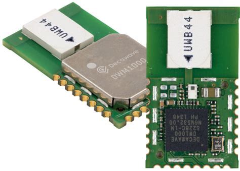
基于DW1000的DWR双向测距调测记录
好久没写嵌入式代码,最近碰到两个数组越界导致程序行为异常的问题,调了近两天,才找到真正的原因,改到开始怀疑人生,到最后柳暗花明,怎么说呢,事出蹊跷必有因!
由于有基线版本,并且基线版本功能是正常的,碰到这种问题,当然先是排除自己的问题(或许是错的,应该先摘除基线版本的问题)!我先把我增加的代码中涉及数组操作的都仔细的滤了一遍,没有发现问题!考虑那就正面刚,先定位问题,所以一通屏蔽代码后,得出的结论是:相同功能的方法,如果用基线版本的,调用程序就运行正常,但换上我重写的方法就有问题,似乎有一种不能做任何修改,改了就出错的错觉!那怎么办,项目进度也有要求,那就先用老方法吧,但是代码不能不动吧,先用老方法,但调试过程中还是有诡异的现象,肿么办??? 事出蹊跷必有因,急不得,慢慢查!!!
ARM程序使用Jlink支持DEBUG的,但调试的过程中程序也会莫名其妙的跳到异常地方,恢复LR、SP的调用栈,也不能找到具体奔溃的位置,踩内存的定位手段确实有限!第一个判断就是肯定是程序哪块越界了,或者是栈溢出导致的异常?好歹也是写过多年C的程序员,早已经从一堆内存的坑里面爬出来了,只是ARM程序内存问题检测工具有限,不然问题也不至于消耗这么长时间处理!
逐一排查代码,发现两个静态数组越界的情况,很简单,但是最开始觉得基线代码起码是稳定的吧,还出这么低级的问题,需要开始时就怀疑一切!:
1、dal_spi.c
#define SPI_TX_BUF_LEN 8
#define SPI_RX_BUF_LEN 255
static uint8_t m_tx_buf[SPI_TX_BUF_LEN] = {0};//居然只有8个字节,使用的时候可远大于8个字节

int dal_spi_xfer(const uint8_t *tx_buf, uint8_t tx_len, uint8_t *rx_buf, uint8_t rx_len){
memcpy(m_tx_buf, tx_buf, tx_len);
}
2、dwOps.c
MAC802154_HEADER_LENGTH长度是23个字节,发POLL消息,消息长度有48个字节,把sendBuf改大了好像出现发不出去dw1000消息了,这个地方怎么改拿不准
static uint8_t sendBuf[16];

static void spiWrite(dwDevice_t* dev, const void *header, size_t headerLength,
                                      const void* data, size_t dataLength)
{
 memcpy(sendBuf, (uint8_t *)header, headerLength);
}基线代码关于UWB测距功能部分代码参考的是开源项目的:lps-node-firmware,但查看开源项目的源码,代码不一样,还是修改出来的问题!github中的源码:
// Aligned buffer of 128bytes
// This is used as a "scratch" buffer to the SPI transfers
// The problem is that the Cortex-m0 only supports 2Bytes-aligned memory access
uint16_t alignedBuffer[64];

static void spiWrite(dwDevice_t* dev, const void *header, size_t headerLength,
                                      const void* data, size_t dataLength)
{
#ifdef DEBUG_SPI
  int i;
  printf("Write to SPI: [ ");
  for (i=0; i<headerLength; i++)
    printf("%02x ", (unsigned int)((uint8_t*)header)[i]);
  printf("] [ ");

  for (i=0; i<dataLength; i++)
    printf("%02x ", (unsigned int)((uint8_t*)data)[i]);
  printf("]\r\n");
#endif

  HAL_GPIO_WritePin(GPIOA, GPIO_PIN_4, 0);

  memcpy(alignedBuffer, header, headerLength);
  HAL_SPI_Transmit(&hspi1, (uint8_t *)alignedBuffer, headerLength, HAL_MAX_DELAY);
  memcpy(alignedBuffer, data, dataLength);
  HAL_SPI_Transmit(&hspi1, (uint8_t *)alignedBuffer, dataLength, HAL_MAX_DELAY);

  HAL_GPIO_WritePin(GPIOA, GPIO_PIN_4, 1);
}
可能是平台不一样,所以基线代码做了修改,但逻辑上确实是有问题,所以使用官方的源码实现重写了SPI的读写方法:
static void spiWrite(dwDevice_t* dev, const void *header, size_t headerLength,
                                      const void* data, size_t dataLength)
{
  #if 0
	memcpy(sendBuf, (uint8_t *)header, headerLength);
	memcpy(sendBuf+headerLength, (uint8_t *)data, dataLength);
	dal_spi_xfer((const uint8_t *)sendBuf, (uint8_t)(headerLength + dataLength),
		NULL, 0);
  #else

  writetospi( headerLength, (const uint8_t *)header, dataLength, (const uint8_t *)data);
  #endif//
	return;
}

static void spiRead(dwDevice_t* dev, const void *header, size_t headerLength,
                                     void* data, size_t dataLength)
{
  #if 0
	dal_spi_xfer((const uint8_t *)header, (uint8_t)headerLength,
		(uint8_t *)data, (uint8_t)dataLength);
  #else

  readfromspi( headerLength, (const uint8_t *)header, dataLength, (uint8_t *)data);
  #endif

	return;
}

//===========================================new api start=====================================================
int readfromspi(uint16_t headerLength, const uint8_t *headerBuffer, uint32_t readlength, uint8_t *readBuffer)
{ uint8_t * p1;
  uint32_t idatalength=0;

  idatalength= headerLength + readlength;

  uint8_t idatabuf[idatalength];
  uint8_t itempbuf[idatalength];

  memset(idatabuf, 0, idatalength);
  memset(itempbuf, 0, idatalength);

  p1=idatabuf;
  memcpy(p1,headerBuffer, headerLength);

  p1 += headerLength;
  memset(p1,0x00,readlength);

  spi_xfer_done = false;
  nrf_drv_spi_transfer(&spi, idatabuf, idatalength, itempbuf, idatalength);
  while(!spi_xfer_done)
  ;

  p1=itempbuf + headerLength;

  memcpy(readBuffer, p1, readlength);

  return 0;
}

int writetospi( uint16_t headerLength, const uint8_t *headerBuffer, uint32_t bodylength, const uint8_t *bodyBuffer)
{
  uint8_t * p1;
  uint32_t idatalength=0;

  idatalength= headerLength + bodylength;

  uint8_t idatabuf[idatalength];
  uint8_t itempbuf[idatalength];

  memset(idatabuf, 0, idatalength);
  memset(itempbuf, 0, idatalength);

  p1=idatabuf;
  memcpy(p1,headerBuffer, headerLength);
  p1 += headerLength;
  memcpy(p1,bodyBuffer,bodylength);

  spi_xfer_done = false;
  nrf_drv_spi_transfer(&spi, idatabuf, idatalength, itempbuf, idatalength);
  while(!spi_xfer_done)
                          ;

  return 0;
}
//===========================================new api end=====================================================
基站每秒处理100个标签的测距性能要求
性能规格要求,基站每秒需要处理100个标签的测距请求,由于DW1000是半双工芯片,同一时刻要么收包、要么发包,不支持同时收发,所以控制并不复杂,一个volatile的状态变量就能搞定互斥了;增加一个标签向基站申请测距的BLINK信令,如果基站这时候空闲,则回复ACK,标识标签可以进行测距了,否则基站将标签的ID放到等待队列中,标签这时候进入等待状态,等到接收到基站的ACK后才开始测距流程,具体流程方案如下:
方案一:基站分时间片服务标签的算法逻辑
标签 基站
Blink -> 基站将该标签地址放到等待队列中
标签发送完blink,进入等待消息状态,等待多久超时,20ms?后继续发送blink
当前基站没有服务的标签,直接回ACK,或者等到当前服务的标签测距完成,才回ACK,标识当前标签可以进入测距流程了
<- Ack
如果超时等待10ms,都没有收到Poll,则从队列中继续出对下一个标签,发送ACK,等待这个标签的测距POLL请求
Poll ->
<- Answer
Final ->
<- Report
测标签到基站的距离
方案二:改进版,少一条ACK的应答,测距对象反过来,测距基站到标签的距离了,但逻辑和结果是一样的。
标签 基站
Blink ->
标签进入等待消息状态
当前没有服务的标签,直接回ACK,或者等到当前服务的标签测距完成,才回Poll,标识当前标签可以进入测距流程了
<- Poll
Answer ->
<- Final
Report ->
测基站到标签的距离
最后实现的逻辑是采用方案一,方案二对比方案一确实是少了一条信令,但是需要调整原来基站代码处理各种接收信令的逻辑,先验证可行性,就先使用了方案一。

-------------------广告线---------------
项目、合作,欢迎勾搭,邮箱:promall@qq.com
本文为呱牛笔记原创文章,转载无需和我联系,但请注明来自呱牛笔记 ,it3q.com
- 上一篇: 给网站增加IP黑名单禁止IP访问
- 下一篇: 凯撒密码的C语言实现,加解密字节流数据

- 最新评论
- 总共0条评论


